

Are you looking to take control of your projects with precision and reliability? Building a PID controller using basic electronic components is easier than you think.
Whether you’re a beginner or have some experience, this guide will show you how to create a controller that can keep your system stable and responsive. By the end, you’ll have the skills to improve everything from temperature control to motor speed.
Ready to unlock the power of PID control and make your electronics smarter? Keep reading, and let’s get started!
Credit: blog.zeptonow.com
Understanding Pid Controllers
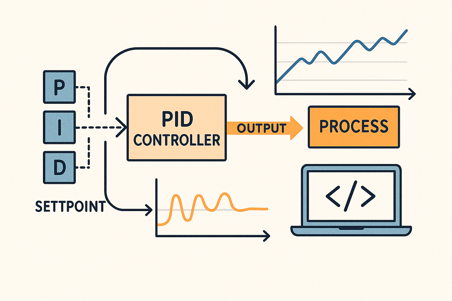
PIDs are common in electronics and control systems. They help machines stay stable and work smoothly. PID means Proportional, Integral, and Derivative. These are three parts that control how a system reacts to changes. Understanding these parts makes building a PID controller easier.
What Is A Pid Controller?
A PID controller keeps a system at a set point. It compares the actual value with the desired value. Then, it adjusts the system to reduce the difference. The goal is to minimize errors and keep things steady.
The Role Of Proportional Control
Proportional control reacts to the current error. It changes output based on how big the error is. A larger error causes a bigger correction. This helps the system respond quickly.
Why Integral Control Matters
Integral control looks at past errors. It adds up all errors over time. This helps remove small, lasting errors. The system becomes more accurate and stable.
How Derivative Control Works
Derivative control predicts future errors. It reacts to how fast the error changes. This reduces overshoot and improves stability. It helps the system avoid sudden jumps.
How Pid Parts Work Together
The three parts combine to control the system well. Proportional gives immediate response. Integral fixes past errors. Derivative prevents sudden changes. Together, they create smooth and precise control.
Key Components Required
Building a PID controller from basic electronic components requires careful selection of parts that work well together. Each component plays a specific role in ensuring your controller performs accurately and reliably. Understanding these key components will help you troubleshoot and fine-tune your design effectively.
Resistors And Capacitors
Resistors control the flow of current and set timing intervals, while capacitors store and release energy to smooth signals. In a PID controller, resistors and capacitors form the backbone of the proportional, integral, and derivative calculations.
Choosing the right values is crucial. For instance, a small change in capacitor size can significantly affect how quickly your controller responds. Have you experimented with different resistor-capacitor combinations to see how they impact your circuit’s behavior?
Operational Amplifiers
Operational amplifiers (op-amps) amplify the input signals and perform mathematical operations needed in PID control. They combine inputs, scale signals, and integrate or differentiate voltage changes over time.
Picking op-amps with low noise and high input impedance improves precision. Don’t overlook the importance of power supply voltage range and slew rate—they can limit your controller’s speed and accuracy. What op-amps have you found reliable in your projects?
Potentiometers
Potentiometers let you adjust the gain of each PID term manually. They act like variable resistors, giving you control over proportional, integral, and derivative settings without changing components.
Using multi-turn potentiometers can give finer control, making tuning easier. Have you tried swapping standard pots for precision versions to improve your tuning experience?
Power Supply
Your power supply provides the necessary voltage and current to all components. A stable and clean power source ensures consistent operation and reduces noise interference in your PID controller.
Consider using regulated power supplies or batteries with filtering capacitors. Have you noticed how fluctuations in power impact your controller’s output stability?
Designing The Pid Circuit
Designing the PID circuit is about combining three essential control actions: proportional, integral, and derivative. Each part plays a unique role in controlling your system’s output effectively. Understanding how to build these parts with basic electronic components will give you full control over your PID controller design.
Proportional Control
The proportional control responds directly to the current error—the difference between your system’s desired setpoint and actual output. You can create this using a simple operational amplifier (op-amp) circuit with a variable resistor to adjust the proportional gain (Kp).
Think of the proportional section as the immediate reaction to an error. If the gain is too high, the output might become unstable. Too low, and the system reacts sluggishly. You can tweak the resistor values until you find the sweet spot that balances speed and stability.
Integral Control
The integral control focuses on eliminating the accumulated error over time. This means it corrects any persistent offset that the proportional control alone can’t fix. To build this, you use an op-amp with a capacitor in the feedback loop, which integrates the error signal.
Choosing the right capacitor and resistor values sets your integral gain (Ki). A higher integral gain speeds up correction but can cause overshoot or oscillations. How often do you find your system drifts away from the target? The integral control is your answer to steady long-term accuracy.
Derivative Control
The derivative control predicts future error based on the current rate of change. This helps dampen the system and reduces overshoot. You can implement this using an op-amp circuit with a capacitor and resistor arranged to differentiate the error signal.
Setting the derivative gain (Kd) requires care—it can amplify noise if not designed properly. But when done right, it smooths out sudden changes and improves system response. Have you noticed jitter or instability in your control system? Adding a derivative element might be the fix you need.
Assembling The Circuit
Assembling the circuit is where your PID controller concept starts to take physical form. This stage requires careful attention to detail to ensure all components work together seamlessly. The way you set up and connect each part can impact your controller’s performance significantly.
Breadboard Setup
Begin by selecting a clean, well-organized breadboard to avoid confusion during assembly. Make sure your breadboard has enough rows and columns to fit all components comfortably. Place it on a stable surface to prevent accidental disconnections.
Consider labeling power rails for easy identification of voltage and ground lines. This simple step saves time and reduces errors during wiring. Have your power supply ready but keep it off until the circuit is fully assembled.
Component Placement
Place your resistors, capacitors, and operational amplifiers close to each other according to the PID schematic. Position the potentiometers where you can easily adjust them during testing. Keep the sensor input and output terminals accessible for quick connection.
Try to minimize the distance between related components to reduce noise and signal loss. I once struggled with a noisy output simply because my capacitors were too far from the op-amps. Small changes in layout can lead to cleaner, more stable signals.
Wiring Connections
Use jumper wires to connect the components following your circuit diagram precisely. Double-check each connection before powering up to avoid shorts or open circuits. Remember, even a single misplaced wire can cause the controller to malfunction.
Organize your wiring neatly by grouping related connections and using different colors for power, ground, and signal lines. This practice helps you troubleshoot faster if something goes wrong. Ask yourself: could you explain your wiring to a friend without the diagram?
Calibrating Your Pid Controller
Calibrating your PID controller is the key to making your system respond smoothly and accurately. It requires careful adjustment of three control elements—proportional, integral, and derivative gains—to balance speed and stability. If you rush this process, your controller might oscillate or react too slowly, so take your time and observe how each change affects your setup.
Tuning Proportional Gain
The proportional gain controls how much the controller reacts to the current error. Too high a value can cause the system to overshoot and oscillate, while too low makes it sluggish. Start by slowly increasing the proportional gain until you notice the output starts to respond quickly but without wild swings.
Ask yourself: is the system correcting errors fast enough without going crazy? If not, dial back the gain or try smaller increments. Watching the response curve on an oscilloscope or logging data can help you see the effect clearly.
Adjusting Integral Action
The integral part fixes steady-state errors by summing past errors over time. This helps your system hit the exact target instead of settling nearby. However, too much integral action can cause slow oscillations or even instability.
Increase the integral gain carefully and observe whether the controller corrects lingering errors without causing bouncing. If you notice the output keeps moving around the setpoint, reduce the integral gain. Precision here makes a big difference in long-term accuracy.
Optimizing Derivative Function
The derivative term predicts future errors by looking at the rate of change. It smooths the controller’s response and helps prevent overshoot. But adding too much derivative gain can amplify noise and make the system jittery.
Start with a low derivative gain and increase it until the output becomes more stable and less prone to overshoot. If the system starts reacting to small fluctuations or becomes noisy, lower it again. Fine-tuning this part often separates a good controller from a great one.
Testing And Troubleshooting
Testing and troubleshooting your PID controller is crucial to make sure it performs as expected in real-world conditions. Without proper checks, even the best-designed circuit can behave unpredictably. This section helps you identify common problems, test effectively, and keep your system stable.
Common Issues
One frequent issue is oscillation, where the output constantly swings instead of settling. This usually happens when the controller gains are too high or not balanced correctly.
Another problem is slow response time, which can occur if the integral or derivative terms are not tuned properly. You might also encounter noise interference affecting the sensor signals, causing erratic behavior.
Have you noticed your output drifting over time? This could point to component tolerances or temperature variations affecting the circuit.
Testing Methods
Start by applying a known input signal and observe the output response. Using an oscilloscope can help you visualize how the controller reacts to changes quickly.
Step responses are particularly useful—you suddenly change the input and watch how the output stabilizes. This gives insight into your proportional, integral, and derivative tuning.
Use a multimeter to verify voltage levels at key points, ensuring components are functioning correctly. Sometimes, simply swapping out a resistor or capacitor can fix unexpected results.
Ensuring Stability
Stability means your PID controller reaches the desired output without continuous oscillation or drift. To achieve this, fine-tune your gain values carefully, starting with the proportional term, then adding integral and derivative adjustments.
Test your controller under different loads and environmental conditions to confirm consistent performance. If you see instability, consider adding a low-pass filter to reduce noise or adjusting your sensor placement.
Ask yourself: Does your system settle quickly without overshoot? If not, recheck your tuning and component quality. Stability isn’t just about numbers—it’s about reliable, repeatable control in your actual setup.
Applications Of Pid Controllers
PID controllers play a vital role in many fields. They help keep systems stable and working smoothly. These controllers adjust variables like temperature, speed, or pressure automatically. This makes machines and devices more efficient and reliable. Below are some common areas where PID controllers are widely used.
Industrial Uses
PID controllers are key in factories and plants. They regulate machines to maintain product quality. Temperature control in ovens and furnaces is one example. They also control pressure in pipelines and flow rates in liquids. This helps reduce waste and energy use. Many industries rely on PID systems for consistent output.
Diy Projects
Hobbyists use PID controllers in home experiments and projects. They build temperature controllers for aquariums or 3D printers. PID systems improve the accuracy of homemade robots and drones. These controllers make DIY devices smarter and more stable. They also teach basic control theory in a practical way.
Automation Systems
Automation depends heavily on PID controllers. They manage robotic arms, conveyor belts, and motors. These controllers keep processes running without human input. They adjust settings to meet target goals smoothly. This reduces errors and increases efficiency in automated setups.

Credit: medium.com

Credit: www.youtube.com
Frequently Asked Questions
What Basic Components Are Needed For A Pid Controller?
To build a PID controller, you need resistors, capacitors, operational amplifiers, and a microcontroller or analog circuit. These components help create proportional, integral, and derivative control actions.
How Does A Pid Controller Improve System Stability?
A PID controller continuously adjusts output based on error, reducing overshoot and steady-state error. It enhances stability by balancing responsiveness and damping.
Can I Build A Pid Controller Without Programming Skills?
Yes, you can build an analog PID controller using basic electronic components and op-amps. This approach requires no programming knowledge.
What Are Common Applications Of Diy Pid Controllers?
DIY PID controllers are used in temperature control, motor speed regulation, and robotics. They offer precise and customizable control for various projects.
Conclusion
Building a PID controller with basic parts is simple and clear. You just need a few common electronic components. Follow the steps carefully and test your circuit often. Adjust the settings to get the best control for your project. This hands-on method helps you learn how PID controllers work.
Keep practicing and experimenting to improve your skills. Soon, you will control systems smoothly and confidently. This project is a great start for anyone interested in electronics and control systems.


