

Are you struggling to recognize electronic components quickly and accurately? Knowing how to identify these parts can save you time, avoid costly mistakes, and boost your confidence whether you’re repairing gadgets or building circuits.
Imagine having a simple, clear PDF guide that breaks down each component with easy explanations and images you can refer to anytime. You’ll discover exactly how to identify electronic components using a handy PDF resource designed just for you. Keep reading, and you’ll unlock the key to mastering electronics like a pro.
Basics Of Electronic Components
Understanding the basics of electronic components is essential for anyone working with electronics. These components form the foundation of all electronic circuits. Each part has a unique role that affects how the entire system functions. Learning their names, shapes, and purposes makes it easier to identify them in diagrams or physical boards.
Electronic components come in many types. They have specific symbols used in circuit diagrams. Recognizing these helps in reading schematics and building circuits correctly. This section introduces common components and their symbols.
Common Types And Their Functions
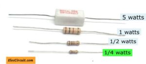
- Resistors:Control electric current flow by providing resistance.
- Capacitors:Store and release electrical energy in circuits.
- Inductors:Store energy in a magnetic field when current passes through.
- Diodes:Allow current to flow in one direction only.
- Transistors:Act as switches or amplifiers for electrical signals.
- Integrated Circuits (ICs):Contain many components like transistors and resistors in one chip.
- Switches:Control the opening or closing of a circuit.
- Batteries:Provide a power source by storing chemical energy.
Symbols And Notations
Electronic components use standard symbols in circuit diagrams. These symbols simplify complex circuits into easy-to-read drawings. Here are some common symbols:
| Component | Symbol | Description |
|---|---|---|
| Resistor | ─/\/\/─ | Represents resistance in a circuit. |
| Capacitor | ─| |─ | Shows two parallel lines for plates storing charge. |
| Diode | ─|▶─ | Triangle with a line, allows current in one direction. |
| Transistor (NPN) | ─|>─ | Arrow shows the direction of current flow. |
| Ground | ─⊥ | Reference point for voltage in circuits. |
Learning these symbols helps in reading and drawing circuit diagrams. It makes electronic projects easier to understand and build.
Credit: www.eleccircuit.com
Tools For Identifying Components
Identifying electronic components accurately requires the right tools. Without them, you might waste time guessing or, worse, damage your circuit. Let’s look at some essential tools that make this task easier and more reliable.
Multimeters And Testers
Multimeters are the backbone of any electronics toolkit. They measure voltage, current, and resistance, helping you confirm if a component matches its specifications.
For example, you can use a multimeter to test a resistor’s resistance or check if a diode is functioning properly. There are also dedicated testers for specific components like transistors or capacitors, which can save you time.
Have you ever struggled to identify a tiny, unmarked component? Using a continuity test or diode check on your multimeter can give you clues about its type and condition. These tools offer quick, hands-on insights into your components’ behavior.
Component Databases
Component databases are digital catalogs packed with detailed information about electronic parts. They include datasheets, pin configurations, and electrical characteristics.
Websites like Octopart or datasheetarchive.com let you search by part number or physical attributes. This is invaluable when you have a component but no idea what it is or how to use it.
Imagine you found a tiny IC with only a partial code visible. Using these databases, you can match what you see against thousands of records to identify it accurately. Have you tried cross-referencing your components with an online database yet? It can save hours of guesswork.
Reading Component Datasheets
Reading component datasheets is crucial to identifying electronic parts correctly. These documents hold detailed information about the component’s features and limits. Knowing how to read them helps you select the right part for your project. Datasheets are often dense, but focusing on key sections simplifies the task.
Key Sections To Focus On
Start with the component overview. It gives a quick summary and typical uses. Next, check the pin configuration or pinout diagram. This shows how to connect the component in a circuit.
Look for the electrical characteristics section. It lists voltage, current, and power ratings. This prevents damage from wrong usage.
Physical dimensions and package type are also important. They ensure the component fits your design.
- Component description
- Pin configuration
- Electrical characteristics
- Package and dimensions
- Absolute maximum ratings
Understanding Specifications
Specifications describe how the component performs. Pay attention to maximum voltage and current ratings. These show the safe operating limits.
Check temperature ranges to ensure the part works in your environment. Note tolerances for resistance or capacitance, showing possible value variations.
Look for typical performance graphs. They illustrate behavior under different conditions. This helps predict real-world performance.
| Specification | Description |
|---|---|
| Voltage Rating | Maximum voltage the component can handle safely |
| Current Rating | Maximum current allowed without damage |
| Temperature Range | Operating temperature limits |
| Tolerance | Acceptable variation in component value |
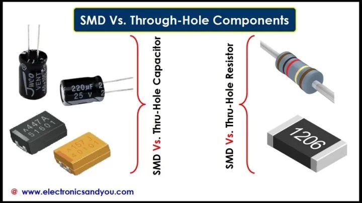
Credit: www.electronicsandyou.com
Decoding Markings On Components
Understanding the markings on electronic components is essential for anyone working with circuits. These tiny codes hold key information about the component’s value, tolerance, and sometimes even its manufacturer. Learning to decode these markings can save you time and prevent costly mistakes in your projects.
Resistor Color Codes
Resistors often use colored bands to indicate their resistance value. Each color corresponds to a number, which you can translate into ohms using a simple chart.
| Color | Number | Multiplier | Tolerance |
|---|---|---|---|
| Black | 0 | 1 | – |
| Brown | 1 | 10 | ±1% |
| Red | 2 | 100 | ±2% |
| Orange | 3 | 1,000 | – |
| Yellow | 4 | 10,000 | – |
| Green | 5 | 100,000 | ±0.5% |
| Blue | 6 | 1,000,000 | ±0.25% |
| Violet | 7 | – | ±0.1% |
| Gray | 8 | – | ±0.05% |
| White | 9 | – | – |
| Gold | – | 0.1 | ±5% |
| Silver | – | 0.01 | ±10% |
For example, if you see a resistor with bands colored red, violet, yellow, and gold, the values correspond to 2, 7, 10,000 multiplier, and ±5% tolerance. This means the resistor value is 270,000 ohms with a 5% tolerance.
Have you ever struggled with identifying a resistor just because the colors were faded? Keeping a color code chart handy or using a multimeter can help you avoid guesswork.
Capacitor Markings
Capacitors often use printed numbers and letters instead of color bands. These markings indicate capacitance, voltage rating, and sometimes the type of capacitor.
- Capacitance:Usually marked in picofarads (pF), nanofarads (nF), or microfarads (µF). For example, “104” means 10 followed by 4 zeros in picofarads, which equals 100,000 pF or 0.1 µF.
- Voltage Rating:Marked as a number followed by “V.” For instance, “50V” means the capacitor can safely handle up to 50 volts.
- Polarity:Electrolytic capacitors have a polarity marking, usually a stripe or a minus sign to indicate the negative lead.
Reading these markings correctly can prevent you from using a capacitor with insufficient voltage tolerance, which might cause failure in your circuit. Have you ever replaced a capacitor only to find it blew out again? Double-checking these codes can save you from repeating the same mistake.
Using Reference Guides And Pdfs
Using reference guides and PDFs makes identifying electronic components easier. These resources provide clear images, symbols, and detailed descriptions. They help beginners and experts understand component functions and specifications quickly. Digital PDFs are easy to carry and search, saving time during projects.
Popular Reference Materials
- Datasheets from manufacturers with detailed specs
- Component identification charts showing shapes and markings
- Electronic symbols guides for circuit diagrams
- Books and manuals on electronics fundamentals
- Online PDF collections from trusted electronics websites
Benefits Of Pdf Guides
- Easy to download and access on various devices
- Searchable text for quick information retrieval
- High-quality images for accurate component recognition
- Printable pages for offline use during hands-on work
- Compact files that do not take much storage space
Tips For Efficient Identification
Identifying electronic components quickly and accurately can save you hours of frustration. Efficient identification not only speeds up your projects but also reduces errors. Here are some practical tips to help you get organized and build a reliable system for recognizing components with ease.
Organizing Your Workspace
Your workspace should invite clarity, not chaos. Arrange components by type or function in clear containers or labeled drawers. This setup lets you spot what you need without digging through piles of parts.
Keep tools like multimeters and datasheets nearby. Having everything within arm’s reach cuts down interruptions and keeps your focus sharp.
Ask yourself: How often do you lose track of small components? A tidy space can prevent that and make your identification process smoother.
Creating A Component Library
Building a personal library of datasheets, PDFs, and reference images creates a go-to resource for quick checks. Organize these files by component categories and include notes on common markings or color codes.
You can also create a physical library with labeled sample parts attached to cards. This hands-on approach helps reinforce your memory and speeds up visual identification.
Think about how often you search online for a datasheet. Having your own well-organized library can save you valuable time and effort during projects.
Common Mistakes To Avoid
Identifying electronic components correctly can be challenging, especially if you rush through the process or overlook critical details in your PDF references. Small mistakes can lead to wrong assumptions, causing delays or even damage to your projects. Understanding common pitfalls helps you avoid these errors and improves your accuracy.
Misinterpreting Data
Electronic component datasheets often contain dense technical information that can be confusing at first glance. You might mistake voltage ratings for current ratings or misread pin configurations because of unfamiliar symbols. Have you ever assumed a component was compatible based on a quick scan, only to find it doesn’t fit your circuit? Take your time to cross-check values like power ratings, tolerance, and temperature limits. This careful reading prevents costly errors.
Also, pay close attention to the units used—milliampere (mA) versus ampere (A) or microfarad (µF) versus nanofarad (nF). A small oversight here can ruin your entire design. Don’t hesitate to use a highlighter or notes on your PDF to mark these critical details.
Overlooking Small Details
Details like package type, pin layout, and even manufacturer notes might seem minor but can drastically affect your component choice. I once missed the difference between a TO-220 and a TO-247 package because I skimmed the diagram. This caused fitting issues on my PCB and delayed the project by days.
Always zoom in on datasheet diagrams and compare them with your component’s physical shape. Look for any special instructions, such as derating curves or maximum junction temperature. These small details are often the difference between a successful build and a frustrating troubleshooting session.
Advanced Identification Techniques
Advanced identification techniques go beyond just reading labels or datasheets. They involve tools and strategies that help you understand components deeply, especially when markings are unclear or missing. These techniques can save you time and prevent costly mistakes during repairs or projects.
Using Circuit Simulation Software
Circuit simulation software can be a game-changer for identifying unknown electronic parts. By inputting the circuit design or partial information, you can test how different components behave in the circuit without physically swapping them.
Many simulation tools allow you to model components based on their specifications. This way, you see how changes in parameters affect the circuit’s performance, helping you narrow down which component fits best.
Have you tried simulating a circuit when a component’s value is uncertain? It often reveals subtle effects that clarify the component’s role, making identification more precise.
Cross-referencing Components
Cross-referencing helps when a component’s marking is faded or unknown. You compare the part with similar ones from different manufacturers to find equivalent specs and characteristics.
Using cross-reference guides or databases, you can match parameters like voltage rating, tolerance, and package type. This approach ensures you pick a compatible replacement or correctly identify the original part.
Think about how many times a simple search in a cross-reference tool saved your project from delays. It’s a practical habit that improves accuracy and speeds up troubleshooting.

Credit: www.electronicsandyou.com
Frequently Asked Questions
What Is The Best Way To Identify Electronic Components?
The best way is using a detailed electronic components PDF guide. It provides symbols, names, and functions clearly. This helps beginners and professionals quickly recognize parts and their uses.
How Can A Pdf Help In Identifying Electronic Components?
A PDF guide offers organized, easy-to-access information about components. It includes images, codes, and specifications that aid recognition. This makes learning faster and more efficient for electronics enthusiasts.
Are There Standard Symbols For Electronic Components In Pdfs?
Yes, standard symbols like resistors, capacitors, and transistors are shown in PDFs. These symbols follow international standards for easy understanding. They simplify reading circuit diagrams and identifying parts accurately.
Where Can I Find Reliable Electronic Components Pdfs?
Reliable PDFs are available on educational websites, electronics forums, and manufacturer sites. Many are free and updated regularly. Always check for the latest version to ensure accuracy.
Conclusion
Identifying electronic components can seem tricky at first. Use the PDF guide to help recognize parts easily. Study shapes, colors, and labels closely. Practice often to build your confidence. Keep the PDF handy for quick reference. Step by step, you will improve your skills.
Simple tools and patience make learning faster. Soon, reading circuit diagrams will feel natural. Keep exploring and enjoy the process of learning.


