How to Inspect Electronic Components: Expert Tips for Accuracy
Are you tired of guessing whether your electronic components are working right? Knowing how to inspect electronic components can save you time, money, and frustration.
Imagine catching a tiny fault before it turns into a big problem. You’ll discover simple, step-by-step ways to check your parts like a pro—no complicated jargon or expensive tools needed. Keep reading, and you’ll gain the confidence to spot issues quickly and keep your projects running smoothly.

Credit: smtmachineline.com
Essential Tools For Inspection
Inspecting electronic components accurately depends largely on having the right tools at your disposal. Without proper equipment, you risk missing critical faults or misjudging the condition of parts. The essential tools listed here will help you perform thorough and reliable inspections, whether you’re troubleshooting a circuit or verifying component quality.
Multimeters And Their Uses
Multimeters are the backbone of electronic inspection. They measure voltage, current, and resistance, giving you quick insights into how a component behaves under electrical conditions. You can check if a resistor matches its rated value or if a diode is functioning correctly by spotting forward and reverse bias behavior.
Using a multimeter to test continuity can save you hours by quickly identifying broken connections or short circuits. I once traced a tiny crack in a circuit board simply by following continuity readings. What simple problem could a multimeter help you solve right now?
Oscilloscopes For Detailed Analysis
Oscilloscopes reveal the waveforms of electronic signals, showing how voltages change over time. This makes them indispensable for diagnosing complex faults in circuits with AC signals or digital pulses. You can see noise, glitches, or unexpected behavior that a multimeter alone cannot detect.
For example, I used an oscilloscope to catch a subtle timing issue in a microcontroller project that caused random resets. Watching the signal live helped me pinpoint the exact moment the fault occurred. Could your next project benefit from visualizing its signals in real time?
Magnifying Tools For Visual Inspection
Sometimes the problem is not electrical but physical—like cracked solder joints or damaged pins. Magnifying tools, such as handheld magnifiers or digital microscopes, let you spot these tiny defects clearly. They help you confirm component authenticity and spot corrosion or debris that might cause trouble.
During a repair job, a magnifier helped me find a barely visible hairline crack in a capacitor’s casing. That small detail was the difference between a lasting fix and a recurring failure. How often do you take a closer look at your components before testing them electrically?

Credit: www.elepcb.com
Identifying Common Components
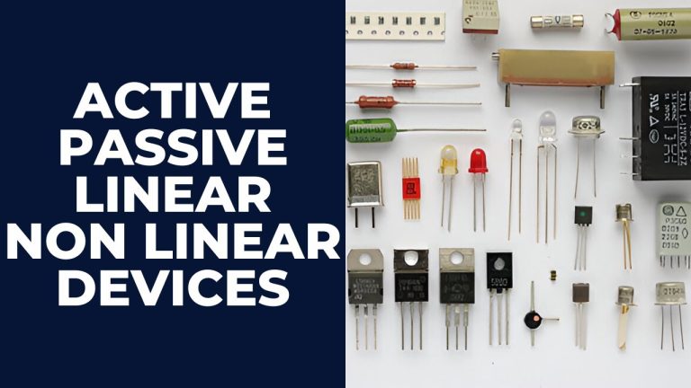
Identifying common electronic components is a crucial skill when inspecting circuits. Knowing what each part does and how to recognize it can save you time and prevent errors. Let’s break down some of the most frequent components you’ll encounter and how to spot their key features.
Resistors And Their Color Codes
Resistors control the flow of electric current by providing resistance. They are usually small cylinders with colored bands wrapped around them. These bands represent numbers that tell you the resistor’s value and tolerance.
Understanding the color code is essential. Each color corresponds to a digit or multiplier. For example, a red band means 2, orange means 3, and gold represents a tolerance of ±5%. You can quickly calculate the resistance by reading the bands in order.
Have you ever struggled with a resistor that didn’t match the expected value? Double-checking the color code often reveals the issue. Carry a color code chart or use a smartphone app to make this easier during inspections.
Capacitors And Polarity Markings
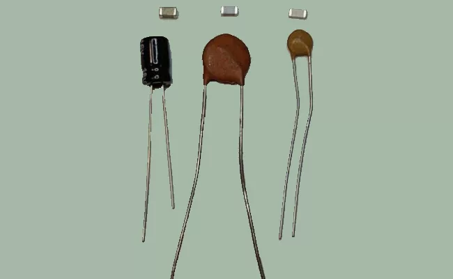
Capacitors store electrical energy and come in many shapes and sizes. Some capacitors are polarized, meaning they have a positive and negative side. Identifying these markings is critical because reversing polarity can damage the component or circuit.
Look for a stripe or minus sign on the body of electrolytic capacitors. This stripe indicates the negative lead. Ceramic capacitors usually don’t have polarity and can be installed in any direction.
When inspecting, always confirm the capacitor’s polarity before testing or replacing it. A simple visual check can prevent costly mistakes and circuit failures.
Ics And Pin Configurations
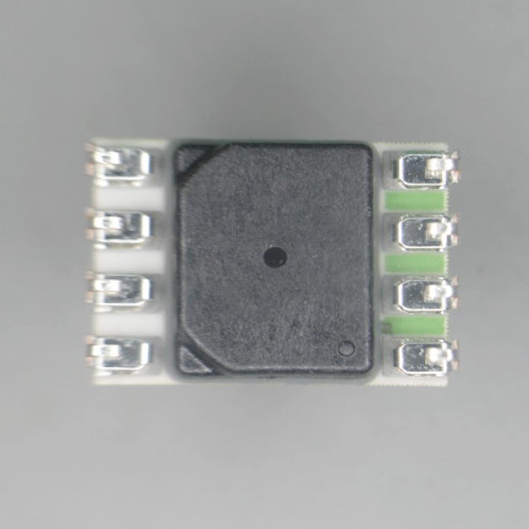
Integrated circuits (ICs) are complex components that house multiple electronic functions. They usually come in rectangular packages with pins on one or more sides. Knowing how to identify the pin 1 position is vital for correct installation and testing.
Look for a dot, notch, or indentation on the IC package. This mark indicates pin 1, and the pins are numbered counterclockwise from that point. Misidentifying the pin layout can cause the circuit to malfunction or damage the IC.
When you first inspect an IC, trace the datasheet to confirm the pin functions. Have you ever installed an IC backward and wondered why it didn’t work? Pin configuration awareness solves that problem every time.
Visual Inspection Techniques
Visual inspection is your first and most straightforward tool for checking electronic components. It helps catch obvious and subtle issues before you power up a device. By training your eyes to spot certain signs, you can save time and prevent bigger problems down the line.
Checking For Physical Damage
Look closely at each component for cracks, chips, or broken parts. Even a tiny crack in a capacitor or resistor can cause failure. Bent or missing pins on ICs (Integrated Circuits) also indicate damage that needs attention.
Don’t overlook the component’s body or leads. Corrosion or rust spots often hint at moisture exposure, which can ruin the part’s function. Touch the component gently—sometimes loose parts don’t look broken but fail under stress.
Identifying Solder Joint Issues
Solder joints connect components to the circuit board, so their quality is critical. Watch for dull, cracked, or uneven solder—these signs usually mean a weak connection. Cold solder joints often look grainy or have tiny holes.
Check if the solder flows smoothly between the component lead and the pad. A good joint is shiny and smooth, without blobs or gaps. If you find joints that look suspicious, consider re-soldering to avoid intermittent failures.
Detecting Burn Marks And Discoloration
Burn marks or color changes on components or the PCB can indicate overheating or electrical shorts. Look for dark spots, smoky residue, or melted plastic around resistors, capacitors, or chips.
Discoloration doesn’t always mean the component is dead, but it signals stress or damage that could worsen. If you spot these signs, ask yourself: has this component been under too much load or faulty conditions?

Credit: www.youtube.com
Testing For Electrical Integrity
Testing for electrical integrity ensures electronic components work correctly. It helps find faults like breaks, shorts, or weak parts. Proper testing saves time and prevents device failure.
Use simple tools like a multimeter to check components. Measuring resistance, capacitance, and semiconductor function reveals hidden issues. These tests are key to reliable electronics.
Measuring Resistance And Continuity
Resistance shows how much a component opposes electric current. Use a multimeter set to resistance mode (ohms). Connect the probes to the component terminals.
Continuity checks if current flows through a path without interruption. Set the multimeter to continuity mode. A beep means the path is complete. No sound means a break.
- Check resistors for correct resistance values.
- Test wires and traces for continuity.
- Identify open or short circuits.
Checking Capacitance And Inductance
Capacitance measures a capacitor’s ability to store charge. Use a multimeter with capacitance mode or a dedicated meter. Connect the leads to the capacitor terminals.
Inductance shows how well a coil stores energy in a magnetic field. Specialized LCR meters measure inductance. Proper values ensure the component works as designed.
- Test capacitors for correct capacitance range.
- Check inductors for expected inductance value.
- Look for damaged or degraded components.
Testing Semiconductor Components
Semiconductors include diodes, transistors, and integrated circuits. Use the diode test mode on a multimeter for simple checks.
Diodes should conduct current in one direction only. Test by placing probes across terminals. Forward bias shows low resistance. Reverse bias shows high resistance.
Transistors need checking of junctions between terminals. Use the diode test mode to verify these junctions behave correctly. Faulty transistors show abnormal readings.
- Test diodes for proper forward and reverse bias.
- Check transistor junctions for correct behavior.
- Use datasheets for reference values.
Advanced Diagnostic Methods
Advanced diagnostic methods offer powerful tools to inspect electronic components beyond basic visual checks. These techniques help you identify hidden faults and assess component performance under real conditions. Using specialized equipment and interpreting technical data can elevate your troubleshooting skills.
Using Thermal Imaging For Heat Detection
Thermal imaging cameras reveal temperature differences across electronic components. Hot spots often indicate issues like short circuits or overloaded parts. When I first used a thermal camera, it helped me spot a resistor overheating before it failed, saving a lot of troubleshooting time.
Heat patterns can guide you to problematic areas without physical contact. This method is especially useful for complex boards where components are tightly packed. Have you checked if any component is hotter than it should be under normal operation?
Signal Tracing With Logic Probes
Logic probes let you follow digital signals through a circuit in real time. They show whether a signal is high, low, or pulsing, which helps verify if components communicate correctly. I once found a faulty microcontroller pin by noticing an unexpected constant low signal on the probe.
Using a logic probe requires patience and steady hands, but it pays off by pinpointing where signals break down. It’s a practical way to trace faults without complex equipment. Could tracking your signals more precisely reduce guesswork in your repairs?
Interpreting Data Sheets And Specifications
Data sheets contain crucial details like voltage limits, pin configurations, and timing requirements. Understanding these specs helps you avoid damaging components and confirms if they operate within safe ranges. I learned that a simple oversight in voltage rating caused repeated failures in a project.
Focus on key sections such as electrical characteristics and recommended operating conditions. Cross-check your measurements against these values for accurate diagnosis. How often do you compare your component readings directly with their data sheets?
Safety Precautions During Inspection
Inspecting electronic components requires more than just a keen eye. Safety must come first to protect both you and the delicate parts you’re handling. Taking the right precautions helps avoid damage and keeps your workspace secure.
Handling Components With Care
Electronic components are fragile and can break easily if dropped or squeezed too hard. Always hold them by the edges or leads to avoid damaging the sensitive parts. If you’ve ever accidentally bent a tiny pin on a chip, you know how frustrating it can be—gentle handling saves time and money.
Use clean, dry hands or tools to prevent contamination. Dirt and oils from your fingers can interfere with electrical connections and cause failures later. Treat each component like a valuable piece of equipment, because it is.
Avoiding Static Electricity Damage
Static electricity can silently destroy electronic components without visible signs. You might think you’re careful, but even walking across a carpet can build up static charge. Have you ever touched a metal object and felt a small shock? That shock could fry sensitive parts.
Use an anti-static wrist strap connected to a grounded surface to discharge static safely. Work on an anti-static mat and keep humidity levels moderate to reduce static build-up. Simple steps like these prevent costly mistakes that often go unnoticed until it’s too late.
Using Protective Gear
Protective gear isn’t just for heavy machinery; it matters when inspecting small electronics too. Safety glasses shield your eyes from unexpected component failures or solder splashes. Gloves can protect your hands from sharp leads and harmful residues.
Choose gloves that don’t generate static and fit snugly to maintain dexterity. Wearing the right gear boosts your confidence and focus, letting you inspect components thoroughly without worrying about injury or contamination.
Frequently Asked Questions
What Tools Are Essential For Inspecting Electronic Components?
Basic tools include a multimeter, magnifying glass, soldering iron, and tweezers. These help check functionality, identify damage, and ensure proper connections.
How Do You Identify Faulty Electronic Components?
Look for discoloration, cracks, burn marks, or corrosion. Use a multimeter to test resistance, continuity, and voltage for accurate diagnosis.
What Safety Precautions Should Be Taken During Inspection?
Always power off devices before inspection. Use anti-static wrist straps to prevent electrostatic discharge. Work in a clean, well-lit environment for safety.
How Can Visual Inspection Improve Component Reliability?
Visual checks help spot physical damage early. Identifying issues like loose connections prevents failure, ensuring components function reliably over time.
Conclusion
Inspecting electronic components helps prevent problems early. Check parts carefully for damage or wear. Use simple tools and follow clear steps. Regular inspections keep devices working well. Learning this skill saves time and money. Stay patient and practice often to improve.
Small details can make a big difference. Keep your electronics safe and reliable this way.