How to Test Electronic Components Using Analog Multimeter: Ultimate Guide
Are you struggling to figure out if your electronic components are working properly? Knowing how to test them with an analog multimeter can save you time, money, and frustration.
This simple skill puts you in control, helping you quickly find faults without guessing. You’ll discover easy-to-follow steps that make testing resistors, capacitors, diodes, and more straightforward than you ever thought. By the end, you’ll feel confident using your analog multimeter to keep your projects running smoothly.
Ready to unlock this valuable skill? Let’s dive in.
Credit: www.kynix.com
Basics Of Analog Multimeter
An analog multimeter is a simple tool used to measure electrical values. It displays results with a needle moving over a scale. This tool helps check voltage, current, and resistance in circuits and components.
Understanding the basics of an analog multimeter is important before testing electronic parts. Knowing its parts and how to read the needle can make testing easier and more accurate.
Components of an Analog Multimeter
- Display:Shows readings with a moving needle.
- Selector Knob:Switches between voltage, current, and resistance modes.
- Probes:Red and black leads used to connect to the circuit.
- Range Selector:Sets the measurement scale for better accuracy.
- Battery:Powers the resistance measurement function.
How to Read the Needle and Scale
The needle moves across the scale to show measurements. The scale changes based on the mode selected. Each scale is marked with numbers and units.
Match the needle position to the correct scale. For voltage, the scale shows volts (V). For current, it shows amperes (A). For resistance, it shows ohms (Ω).
Setting the Range Correctly
Always start with the highest range. This prevents damage to the meter. If the reading is too low, switch to a lower range.
Using the correct range gives a clear and precise reading. Avoid guessing the range as it may cause wrong results.
Essential Multimeter Features
Understanding the essential features of an analog multimeter is key to testing electronic components accurately. These features help you measure voltage, current, and resistance effectively. Knowing how to use them prevents errors and protects your components.
Understanding The Scale
The scale shows different measurement ranges. It has markings for volts, ohms, and amps. Each scale section is calibrated differently. Always read the correct scale for your test. The needle moves across the scale to give readings. Small divisions mean more precise measurements.
Probes And Connections
Probes are the wires that connect the multimeter to the component. One probe is usually red for positive. The other is black for negative or ground. Insert probes into the correct ports on the multimeter. Tight, clean connections ensure accurate results. Hold probes steady during testing to avoid errors.
Range Selection
Range selection lets you choose the measurement scale. Set the range higher than the expected value. This prevents damage to the multimeter. If unsure, start with the highest range and move lower. Correct range setting gives clearer, more stable readings. Some analog meters have manual range switches to adjust.
Safety Precautions
Safety is the top priority when testing electronic components with an analog multimeter. Taking the right precautions protects you and your devices. Simple safety steps prevent accidents and damage.
Before starting, always check the multimeter and probes for damage. Worn or broken parts can cause shocks or wrong readings. Use insulated tools and wear rubber-soled shoes to reduce electrical risk.
Inspect Equipment Before Use
- Check the multimeter for cracks or loose parts.
- Examine test leads and probes for exposed wires or damage.
- Ensure the dial and switches work smoothly.
Disconnect Power From Circuits
- Turn off power before connecting the multimeter.
- Discharge any capacitors to avoid shocks.
- Never test components in a live circuit unless specified.
Use Proper Multimeter Settings
- Select the correct measurement type (voltage, resistance, current).
- Set the range higher than expected values to avoid damage.
- Confirm the multimeter is on the right mode before testing.
Avoid Contact With Live Wires
- Hold probes by insulated handles only.
- Keep fingers behind the probe guards.
- Do not touch metal parts during measurements.
Work In A Safe Environment
- Use a dry, clean workspace free of clutter.
- Avoid testing near water or in damp conditions.
- Keep flammable materials away from electrical work.

Credit: www.youtube.com
Testing Resistors
Testing resistors with an analog multimeter is a straightforward way to check if they function properly or need replacement. Resistors control the flow of electric current, so ensuring their accuracy is key to keeping your circuits working well. With a few simple steps, you can quickly identify if a resistor matches its specified value or has drifted out of tolerance.
Setting The Multimeter
Start by turning your analog multimeter to the resistance (Ω) setting. Most analog meters have several resistance ranges, so choose one that best fits the resistor’s expected value.
- If you’re testing a 1kΩ resistor, select the 2kΩ or 20kΩ range to get a clear reading.
- For smaller resistors, use a lower range like 200Ω to increase measurement accuracy.
Don’t forget to zero your meter before testing. Touch the two probes together and adjust the needle to zero on the scale to avoid inaccurate readings.
Reading Resistance Values
Connect the probes to each end of the resistor. It doesn’t matter which probe goes where because resistance is not polarized.
Watch the needle move on the dial. The pointer will settle on the scale showing the resistor’s value.
| Resistor Value | Meter Range | Expected Needle Position |
|---|---|---|
| 1kΩ | 2kΩ | Near the middle of the scale |
| 10kΩ | 20kΩ | Just before the end of the scale |
| 100Ω | 200Ω | About halfway on the scale |
If the needle doesn’t move or sticks to zero, the resistor might be open or shorted. Have you ever found a resistor that looked fine but tested completely off? That moment reminds you why this simple test saves time and prevents bigger headaches later.
Testing Capacitors
Testing capacitors with an analog multimeter is a straightforward process that can save you time and money when troubleshooting electronic circuits. Capacitors store electrical energy, so handling them carefully is essential to avoid shocks or damage to your meter. Understanding how to properly discharge and check capacitance ensures accurate readings and helps identify faulty components quickly.
Discharging The Capacitor
Before testing, you must discharge the capacitor to prevent any stored charge from affecting your multimeter or causing injury. Use a screwdriver with an insulated handle or a resistor to short the capacitor leads gently.
Touch both leads of the capacitor simultaneously with the tool, and hold it for a few seconds. This action safely releases any stored energy.
Have you ever felt a small shock from a capacitor you forgot to discharge? Taking this step seriously protects both you and your equipment.
Checking Capacitance
Set your analog multimeter to the highest resistance range, often labeled as “Rx1k” or similar. Connect the multimeter probes to the capacitor leads—polarity matters if you’re testing an electrolytic capacitor.
Watch the needle carefully. A good capacitor will cause the needle to jump towards zero resistance and then slowly move back to infinity as it charges. This behavior indicates the capacitor is accepting and holding charge properly.
If the needle stays at zero or infinity without moving, the capacitor is likely shorted or open, respectively. Testing this way gives you quick, reliable insight into the capacitor’s health without needing specialized tools.
Testing Diodes
Testing diodes with an analog multimeter helps check their condition quickly. Diodes allow current to flow in one direction only. They block current in the opposite direction. This property makes testing diodes simple and effective. Two tests are key: forward bias and reverse bias. These tests show if the diode works or is damaged.
Forward Bias Test
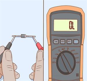
Set the multimeter to the resistance or diode test mode. Connect the red probe to the diode’s anode. Connect the black probe to the cathode. The meter should show a low resistance or a voltage drop. This means current flows through the diode. It confirms the diode is good in forward bias.
If the meter shows very high resistance or no reading, the diode is faulty. It might be open or damaged inside. Repeat the test to confirm the result.
Reverse Bias Test
Reverse the probes on the diode. Connect the black probe to the anode and the red probe to the cathode. The multimeter should show very high resistance or no current. This proves the diode blocks current in reverse bias.
If the meter shows low resistance or a voltage drop, the diode is shorted or defective. It allows current both ways, which is wrong for a diode. This test ensures the diode blocks current properly in reverse bias.
Testing Transistors
Testing transistors with an analog multimeter helps find faulty parts quickly. Transistors control current in circuits and must work correctly. The analog multimeter measures voltage and resistance to check transistor health. It shows if the transistor switches properly or has internal damage.
Identifying Transistor Type
Transistors come in two main types: NPN and PNP. Knowing the type helps test them correctly. Look for the part number printed on the transistor body. Search online for its datasheet to confirm the type and pin layout.
If no label is visible, test with the multimeter’s diode mode. The transistor has three pins: emitter, base, and collector. The base-emitter and base-collector junctions act like diodes. By checking these junctions, you can guess the transistor type.
Checking Npn And Pnp Transistors
Set the multimeter to diode test mode. Identify the base pin by testing forward voltage drop between pins. For an NPN transistor:
- Place the positive lead on the base.
- Touch the negative lead to emitter and collector pins.
- Both readings should show a voltage drop (around 0.6 to 0.7 volts).
Reverse the leads to check for no conduction.
For a PNP transistor:
- Place the negative lead on the base.
- Touch the positive lead to emitter and collector pins.
- Both readings should show a voltage drop.
Reverse leads should show no conduction.
Short circuits or open readings indicate a faulty transistor. Always compare readings with a known good transistor for best results.

Credit: www.ersaelectronics.com
Testing Inductors
Testing inductors with an analog multimeter helps check their condition and function. Inductors store energy in a magnetic field when current passes through. Over time, they may develop faults like short circuits or open windings. Using an analog multimeter, you can quickly spot these issues and verify if the inductor works properly.
Assessing Inductance
Analog multimeters do not measure inductance directly. But you can check the coil’s resistance to estimate its condition. Set the multimeter to the ohms (Ω) range. Connect the probes to the inductor leads. A low resistance value means the coil is intact. Very high or infinite resistance suggests a broken wire inside the coil. Zero or near zero resistance might indicate a shorted turn.
For more accurate inductance testing, an LCR meter is needed. Still, resistance checks help find many common problems quickly.
Identifying Faults
Use the analog multimeter to find these common inductor faults:
- Open circuit:No needle movement or infinite resistance means the coil is broken.
- Short circuit:Needle jumps to zero ohms showing a short inside the coil.
- Partial damage:Unusual resistance values or fluctuating needle indicate coil damage.
Also, check for physical damage like burns or broken terminals. These signs often point to faulty inductors needing replacement.
Troubleshooting Common Issues
When you test electronic components with an analog multimeter, unexpected results can be frustrating. Troubleshooting common issues helps you save time and avoid misdiagnosis. Understanding what unusual readings mean and ensuring your multimeter is properly calibrated are key steps to get accurate measurements.
Interpreting Unusual Readings
Sometimes, your multimeter needle might jump erratically or show zero resistance on a component you expect to have some. This could mean the component is faulty or your connections aren’t secure. Double-check your probe contacts and make sure you’re testing the component in the right mode.
If the reading seems too high or too low, consider environmental factors like temperature or interference from nearby components. Capacitors, for example, may show a brief needle movement before settling, which is normal behavior. Have you noticed that certain resistors give inconsistent readings? This might indicate damage or tolerance issues.
Always compare your results with component specifications. If you’re testing a diode, the needle should move in one direction only. Reading a deflection in both directions often signals a damaged diode. Keep a simple reference chart handy for quick cross-checking.
Multimeter Calibration
Your multimeter needs to be calibrated regularly to provide accurate readings. An uncalibrated meter can mislead you, causing unnecessary replacements or repairs. Calibration involves adjusting the meter’s zero and span settings based on known standards.
Start by setting the meter to the resistance mode and shorting the probes together. The needle should rest exactly at zero; if not, adjust the zero control knob. Next, test a known resistor value to check if the reading matches the expected resistance.
If your multimeter doesn’t have easy calibration controls, consider having it professionally serviced. Calibration ensures your measurements reflect reality, not just what the needle randomly shows. How often do you verify your tool’s accuracy before a critical test?
Maintaining Your Analog Multimeter
Maintaining your analog multimeter is essential to keep it accurate and reliable. Regular care prevents errors and extends the life of your device. You’ll find that a well-maintained multimeter works smoothly every time you need it.
Regular Cleaning
Dust and dirt can build up on your analog multimeter, especially on the dial and probes. Use a soft, dry cloth to wipe the exterior regularly. Avoid harsh chemicals that might damage the plastic or the internal parts.
Cleaning the probe tips is just as important. Dirty or corroded tips can cause inaccurate readings. Gently rub the tips with fine sandpaper or a pencil eraser to remove any oxidation.
Have you noticed your readings fluctuating unexpectedly? Cleaning the contacts inside the multimeter might help. Carefully open the case and use compressed air or a small brush to clear dust from the internal components.
Battery Replacement
Your analog multimeter’s battery powers the internal circuitry, so a weak battery can lead to false readings. Check the battery regularly and replace it as soon as you notice dim needle movement or no response.
Always use the correct battery type recommended by the manufacturer. Using the wrong battery can damage the device or reduce its lifespan.
When changing the battery, handle it with care to avoid spilling any acid or damaging the contacts. Dispose of old batteries properly—never throw them in the trash.
Have you ever struggled to get a clear reading only to find the battery was the problem? Keeping spare batteries handy can save you time and frustration during testing.
Frequently Asked Questions
How Do I Test Resistors With An Analog Multimeter?
To test resistors, set the multimeter to the ohm scale. Connect probes across the resistor leads. A stable reading matching the resistor value indicates it’s good.
Can I Test Capacitors Using An Analog Multimeter?
Yes, but only basic checks. Set multimeter to the ohm scale and watch for charging behavior. A rising resistance reading suggests a good capacitor.
How To Check Diodes With An Analog Multimeter?
Set the multimeter to the diode test or low ohm scale. Connect probes to diode terminals. A low reading in one direction and high in reverse indicates a good diode.
What Precautions Should I Take When Testing Components?
Always disconnect power before testing. Discharge capacitors fully. Use proper multimeter settings and handle probes carefully to avoid damage.
Conclusion
Testing electronic components with an analog multimeter is simple and useful. This tool helps find problems fast and saves money on repairs. Always set the meter correctly before starting tests. Check resistors, capacitors, and diodes carefully for accurate results. Practice often to feel confident using the multimeter.
Small steps lead to better skills and understanding. Keep your multimeter safe and clean for a long life. This basic skill helps with many electronic projects and fixes. Give it a try, and see how easy testing can be.