How to Check Electronic Components: Easy Steps for Accurate Testing
Are you struggling to know if your electronic components are working properly? Whether you’re fixing a gadget or building a new project, checking these parts is crucial.
But how do you make sure each component is reliable without wasting time or money? You’ll discover simple and effective ways to test your electronic components quickly and accurately. By the end, you’ll feel confident handling your devices and avoid costly mistakes.
Keep reading to unlock the secrets of checking electronic components like a pro!
Basic Tools For Testing
Testing electronic components requires having the right tools at your disposal. Without them, you might misread results or damage sensitive parts. Let’s look at some basic tools that will make your testing more accurate and efficient.
Multimeter Essentials
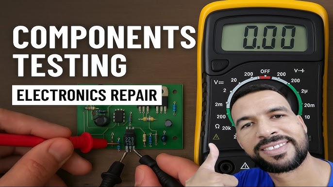
A multimeter is your first line of defense for checking components like resistors, capacitors, and diodes. It measures voltage, current, and resistance with ease. Make sure your multimeter has a clear display and multiple testing modes to cover different components.
Look for features such as continuity testing and diode check. They save time by quickly identifying broken connections or faulty diodes. Have you noticed how a simple beep can confirm a complete circuit instantly?
Oscilloscope Basics
Oscilloscopes let you see electronic signals in real-time. This is crucial when you want to analyze waveform shapes, frequencies, and noise in a circuit. Even if you’re new to oscilloscopes, starting with a basic model can reveal a lot about how your components behave under different conditions.
Try capturing the signal from a capacitor charging or a transistor switching on and off. Watching these waveforms helps you understand if components operate correctly or need replacement. What patterns would you expect to see in a healthy versus a faulty signal?
Soldering Equipment
Good soldering tools are essential not only for assembling circuits but also for removing and testing components safely. A quality soldering iron with adjustable temperature control protects delicate parts from heat damage. Pair it with solder wick or a desoldering pump to cleanly remove solder without stressing the board.
Investing in proper soldering equipment makes testing and repairs smoother. Have you ever struggled with a cold solder joint that caused intermittent problems? Proper tools reduce those headaches significantly.
Safety Measures
Checking electronic components involves working with delicate parts and potentially hazardous equipment. Prioritizing safety measures protects both you and your devices from damage. Understanding proper safety protocols ensures you handle components confidently and avoid costly mistakes.
Handling Precautions
Always discharge static electricity before touching electronic components. You can do this by touching a grounded metal object or using an anti-static wrist strap. Static shocks might seem harmless, but they can instantly ruin sensitive chips.
Handle components by their edges instead of the pins or solder joints. This reduces the risk of bending pins or contaminating connections with oils from your fingers. Have you ever noticed how a tiny fingerprint can interfere with a circuit’s performance?
Work on a clean, non-conductive surface to prevent accidental shorts. Avoid stacking components or placing them near liquids. Simple habits like these can save you from troubleshooting headaches later.
Protective Gear
Wearing the right protective gear is not just about safety; it’s about precision. Use safety glasses to shield your eyes from solder splashes or tiny flying debris when testing or repairing.
Gloves can protect your hands from sharp leads and harmful chemicals, but choose ones that don’t reduce your dexterity. Nitrile gloves offer a good balance, allowing you to feel the components while staying protected.
Consider a mask if you’re soldering in a poorly ventilated area. Solder fumes can irritate your respiratory system, and prolonged exposure may cause health issues. Have you checked if your workspace has adequate ventilation?
Identifying Components
Identifying electronic components accurately is crucial before you test or replace them. Each component has unique markings and shapes that tell you what it is and how it behaves in a circuit. Recognizing these details saves time and prevents mistakes in your projects.
Resistors And Capacitors
Resistors usually have colored bands that indicate their resistance value. You can use a color code chart to decode these bands quickly. Capacitors come in different shapes—some are small cylinders, others flat rectangles—and they often have their capacitance printed directly on them.
Pay attention to polarity in capacitors; electrolytic types will have a clear positive or negative marking. If you’re unsure, checking the datasheet or component packaging can help confirm the values. Have you ever mixed up resistor values because you misread the color bands? It happens more often than you think.
Diodes And Transistors
Diodes are marked with a stripe at the cathode end, showing current direction. Transistors can look similar but usually have three leads and a flat side or tab that helps identify the collector, base, and emitter. Learning to recognize these physical features helps you place them correctly in a circuit.
Testing a diode with a multimeter can verify its forward and reverse bias behavior, but knowing which end is which saves you time. Transistors often have part numbers printed on their bodies—searching those numbers online gives you detailed specs instantly.
Integrated Circuits
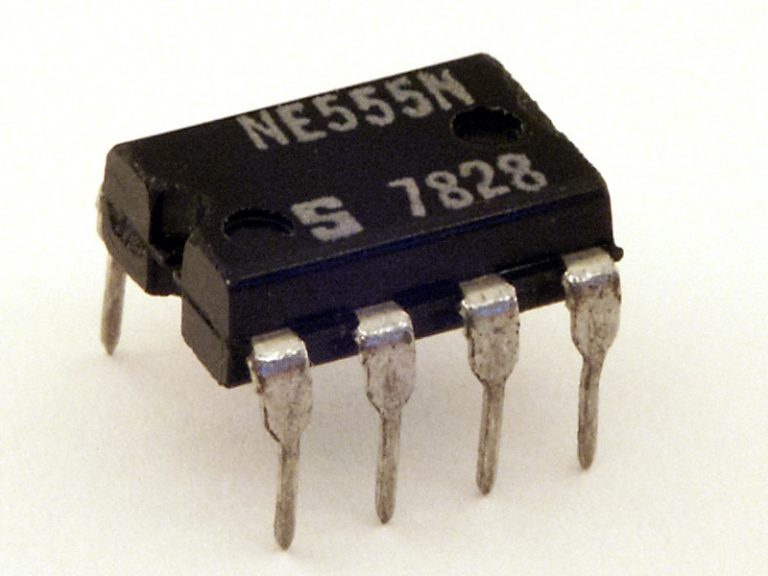
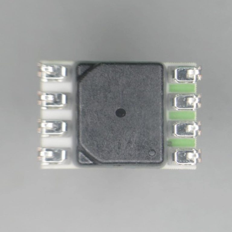
Integrated circuits (ICs) vary widely in size and shape but usually have a part number printed on top. That number is your key to finding pin configurations and datasheets. Look for a notch or dot to identify pin 1; this is essential for proper orientation.
Sometimes ICs look nearly identical but serve very different functions. Cross-checking the part number before installation prevents costly errors. Have you ever spent hours troubleshooting only to find an IC inserted backward? Checking the orientation first can save you that headache.

Credit: www.youtube.com
Testing Resistors
Testing resistors is a fundamental skill that can save you time and frustration when working with electronic components. Resistors control the flow of electric current, so knowing how to check their condition ensures your circuit performs correctly. Let’s break down how you can measure resistance and spot common issues that might affect your resistors.
Measuring Resistance
To measure a resistor’s resistance, you’ll need a digital multimeter set to the ohm (Ω) scale. First, remove the resistor from the circuit or ensure the circuit is powered off to avoid inaccurate readings.
Touch the multimeter probes to each end of the resistor. The display shows the resistance value. If the reading matches the resistor’s labeled value within tolerance, it’s good to go.
Have you noticed how sometimes the reading fluctuates? This can indicate a loose connection or a damaged resistor. Always test multiple times for consistency.
Common Issues
Resistors can fail in several ways. They might become open (no continuity), shorted (very low resistance), or drift out of their specified tolerance due to heat or age.
Look for visible signs like burns, discoloration, or cracks. These often point to a resistor that needs replacement. But remember, some issues aren’t visible and only show up through testing.
Consider this: a resistor that reads within tolerance but causes circuit problems might still be faulty under load. Testing only resistance values sometimes isn’t enough, so check the component in operation if possible.
Capacitor Testing Techniques
Capacitors store electrical energy and play a key role in circuits. Testing them ensures they work correctly and safely. Faulty capacitors can cause device failures or damage. There are simple ways to check their condition using common tools.
Checking Capacitance
Capacitance shows how much charge a capacitor can hold. Use a digital multimeter with a capacitance setting. First, disconnect the capacitor from the circuit. Discharge it safely by shorting its leads with a resistor.
Set the meter to the capacitance mode. Connect the meter probes to the capacitor leads. The reading should match the capacitor’s rated value on its body. A significant difference means the capacitor may be bad.
Detecting Leaks
Leaking capacitors lose charge and cause circuit problems. Visual checks help spot leaks. Look for bulging tops, corrosion, or wet spots on the capacitor body.
Use a multimeter in resistance mode to test leakage. Place the probes on the capacitor leads. A very low resistance reading suggests a leak. The capacitor should normally show high resistance.
Diode And Transistor Tests
Testing diodes and transistors is key to ensure electronic components work correctly. These tests help find faults and verify if parts meet their specifications. Simple tools like a multimeter can perform these checks accurately.
Understanding how diodes and transistors behave under different conditions is important. You can check if a diode allows current in one direction and blocks it in the other. For transistors, measuring their gain shows how well they amplify signals.
Forward And Reverse Bias
Diodes conduct current only in one direction. To test a diode, apply a forward bias by connecting the positive lead of a multimeter to the diode’s anode and the negative lead to the cathode. A low resistance or a voltage drop between 0.6V and 0.7V usually means the diode is good.
Next, reverse the leads for a reverse bias test. A good diode shows very high resistance or no conduction at all. If the diode conducts both ways, it is likely damaged.
- Set the multimeter to diode mode.
- Connect the red lead to the anode and the black lead to the cathode.
- Note the forward voltage drop reading.
- Reverse the leads to check for no conduction.
Transistor Gain Measurement
Transistor gain, or hFE, shows how much the transistor amplifies current. This test requires a multimeter with an hFE function or a simple transistor tester.
Insert the transistor leads into the correct hFE socket based on its type (NPN or PNP). The meter will display the gain value. Typical values range from 20 to 300, depending on the transistor model.
- Identify transistor type (NPN or PNP).
- Place leads in corresponding hFE slots.
- Read the gain value on the meter.
- Compare with the transistor’s datasheet.
Testing gain helps confirm the transistor’s ability to amplify signals properly. Low or zero gain often indicates a faulty transistor.
Integrated Circuit Evaluation
Evaluating integrated circuits (ICs) is essential when you want to ensure your electronic projects work reliably. These tiny chips control many functions, so checking them carefully saves you from hours of troubleshooting. Understanding how to test their function and verify pin integrity can help you spot faulty components before they cause problems.
Functional Testing
Functional testing checks whether an integrated circuit performs its intended operations correctly. You can use a simple test circuit or a specialized IC tester to apply power and signals, then observe the output.
For example, if you are testing a timer IC like the 555, set it up in a basic astable configuration. Measure the output pulse frequency with a multimeter or oscilloscope. If the frequency matches expected values, the IC is likely working fine.
Have you noticed how sometimes an IC looks perfect but fails functional tests? That’s a clear sign to replace it rather than waste time on guesswork.
Pin Integrity Checks
Pin integrity is crucial because bent, broken, or shorted pins can cause failures even if the IC itself is fine. Start by visually inspecting each pin under good lighting or a magnifier.
Use a multimeter to check for continuity between adjacent pins to detect shorts. Also, verify there’s no unexpected resistance between pins that should be isolated.
Gently wiggle each pin to see if it’s loose or damaged—this simple step often reveals connection issues before you solder the IC onto your board.
Troubleshooting Tips
Troubleshooting electronic components requires careful observation and a clear process. It helps to understand common issues and how to fix them. This section guides you through simple ways to spot faults and repair components effectively.
Identifying Faults
Start by looking for visible damage like burns or cracks. Use a multimeter to check for breaks in circuits or unusual resistance. Listen for unusual sounds from components, such as buzzing or clicking. Smell can also help; a burnt smell often means a failed part. Check connections for looseness or corrosion, which can cause problems.
- Visual inspection for damage
- Measure voltage and resistance
- Listen for abnormal sounds
- Smell for burnt parts
- Check all connections
Repair Strategies
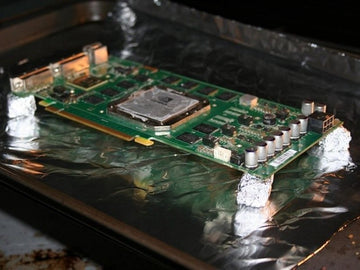
Replace damaged components with exact or compatible parts. Clean corroded contacts using isopropyl alcohol and a brush. Re-solder loose connections carefully to restore contact. Use a heat gun to reflow solder on circuit boards if needed. Test the component again after repair to ensure it works properly.
- Replace faulty parts
- Clean corrosion
- Re-solder connections
- Reflow solder with heat gun
- Retest repaired components
Advanced Testing Techniques
Advanced testing techniques give you a deeper insight into how your electronic components perform under real conditions. They help identify hidden faults that basic tests might miss, saving you time and preventing costly replacements. With the right tools, you can pinpoint issues quickly and confidently.
Using Logic Analyzers
Logic analyzers are essential for examining digital signals in complex circuits. They capture and display multiple signals simultaneously, allowing you to see how data flows through your components in real time.
If you’ve ever struggled to find why a microcontroller isn’t responding, a logic analyzer can reveal timing errors or glitches you might not detect otherwise. You connect probes to the circuit, set triggers for specific signal patterns, and watch the data unfold on your screen.
Consider this: how often do you rely solely on multimeters for digital troubleshooting? A logic analyzer adds a new dimension by letting you observe the logic states and timing relationships, which is crucial for debugging communication buses like SPI, I2C, or UART.
Thermal Imaging For Diagnostics
Thermal imaging cameras show temperature variations across your electronic components. Overheating parts can indicate problems like short circuits, excessive current draw, or faulty connections.
I’ve seen thermal images reveal a tiny resistor heating up before it fails completely, saving a project from downtime. You simply scan the circuit board and look for hotspots that stand out from the normal temperature range.
What if you could catch a failing component before it blows out? Thermal imaging lets you do just that by highlighting abnormal heat patterns early on, giving you a chance to intervene before damage spreads.

Credit: www.youtube.com

Credit: www.youtube.com
Frequently Asked Questions
How Do I Test Electronic Components At Home?
You can test electronic components using a multimeter. Check resistance, voltage, and continuity to verify functionality. Follow safety precautions and component datasheets for accurate testing.
What Tools Are Needed To Check Electronic Components?
Essential tools include a digital multimeter, soldering iron, component tester, and a breadboard. These help measure electrical properties and test circuit connections efficiently.
How Can I Identify Faulty Electronic Components?
Look for physical damage, discoloration, or burnt smell. Use a multimeter to test continuity and resistance. Faulty components often show open circuits or abnormal readings.
Can I Test Electronic Components Without A Circuit?
Yes, many components like resistors, capacitors, and diodes can be tested individually using a multimeter. Ensure the component is disconnected from the circuit before testing.
Conclusion
Checking electronic components is easy with the right steps. Use a multimeter to test resistors, capacitors, and diodes. Always turn off power before testing parts. Look for signs of damage or wear. Testing helps find faulty parts quickly and saves time.
Practice often to build confidence and skill. Soon, you will feel comfortable checking most components yourself. Simple tools and careful checks make repair work smoother. Keep learning and stay curious about electronics. This skill helps in many projects and fixes.