How to Test Electronic Components With a Multimeter Pdf: Ultimate Guide
Are you struggling to know if your electronic components are working properly? Testing them with a multimeter can save you time, money, and frustration.
But if you’re new to this, it might seem confusing or overwhelming. Don’t worry—this guide will walk you through the steps clearly and simply. Plus, you’ll get a handy PDF to keep as a reference whenever you need it. By the end, you’ll feel confident checking resistors, capacitors, diodes, and more, so your projects run smoothly every time.
Ready to become your own electronics expert? Let’s dive in!
Multimeter Basics
Understanding multimeter basics is essential for testing electronic components accurately. A multimeter measures electrical values like voltage, current, and resistance. It helps identify faulty parts quickly and safely. Knowing the types and features of multimeters makes testing easier and more efficient.
Types Of Multimeters
- Analog Multimeter:Uses a needle to display readings on a scale. It is simple but less precise.
- Digital Multimeter (DMM):Shows readings as numbers on a screen. It is more accurate and easy to read.
- Auto-Ranging Multimeter:Automatically selects the correct measurement range. Ideal for beginners.
- Manual-Ranging Multimeter:Requires manual range selection. Offers more control for experienced users.
Key Functions And Features
- Voltage Measurement:Measures AC and DC voltage in circuits.
- Current Measurement:Detects the flow of electric current through a component.
- Resistance Measurement:Tests how much a component resists electrical flow.
- Continuity Test:Checks if a circuit is complete without breaks.
- Diode Test:Verifies if diodes allow current in one direction.
- Hold Function:Freezes the reading on the display for easy recording.
- Backlight:Illuminates the screen for use in low light.
Safety Precautions
Testing electronic components with a multimeter requires careful attention to safety. Ignoring safety rules can lead to damage or injury. Always prepare your workspace and tools before starting. Understanding safety helps protect you and your components.
Handling Electronic Components
Handle all components gently. Avoid touching metal leads directly with your fingers. Oils and static can damage sensitive parts. Use anti-static wrist straps or mats when possible. Keep components in anti-static bags until use. Store parts in organized containers to prevent loss or damage.
Avoiding Common Hazards
- Always disconnect power before testing.
- Check multimeter settings carefully before use.
- Do not test components in a live circuit unless specified safe.
- Watch for sharp leads or broken parts that can cause cuts.
- Keep liquids away from your work area to prevent electric shock.
- Use insulated tools to avoid accidental shorts.
Testing Resistors
Testing resistors is an important part of checking electronic circuits. Resistors control current flow by adding resistance. Checking their values ensures the circuit works correctly. A multimeter helps measure this resistance easily and accurately.
Before measuring, understanding resistor values is key. Each resistor has color bands that show its value. Knowing how to read these bands saves time and prevents errors in testing.
Identifying Resistor Values
Resistors have colored bands that represent numbers. Each color stands for a digit or multiplier. The first two bands show significant digits. The third band shows the multiplier. The last band indicates tolerance, or how much the value can vary.
For example:
- Brown = 1
- Red = 2
- Orange = 3
- Yellow = 4
- Green = 5
- Blue = 6
- Violet = 7
- Gray = 8
- White = 9
Multipliers are powers of ten based on the third band. A red band means multiply by 100. A gold band means multiply by 0.1. Use a resistor color chart for quick reference.
Measuring Resistance
To measure resistance, set the multimeter to the resistance mode (Ω). Connect the probes to each end of the resistor. The reading shows the resistance value in ohms.
Keep these tips in mind:
- Remove the resistor from the circuit if possible.
- Avoid touching metal parts with your fingers.
- Check the multimeter battery for accurate readings.
- Compare the reading with the resistor’s rated value.
A reading close to the rated value means the resistor is good. A very different reading indicates a damaged resistor. Testing resistors with a multimeter helps find faults in electronic devices quickly.
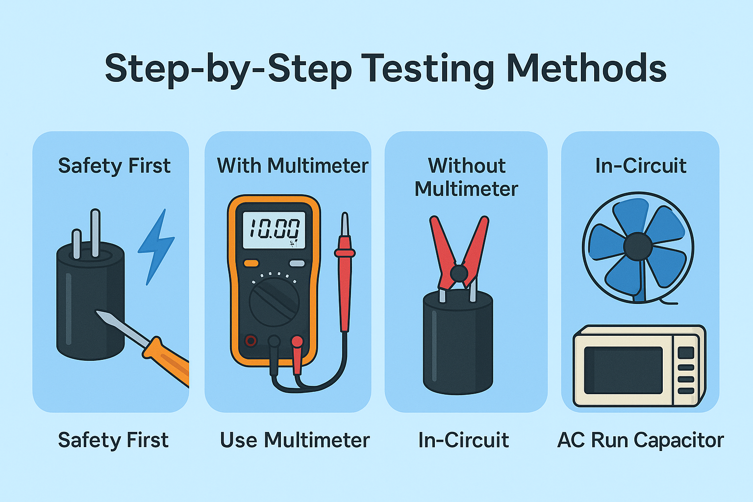
Credit: www.ersaelectronics.com
Testing Capacitors
Testing capacitors is a vital task to ensure they work well in electronic circuits. Capacitors store and release electrical energy. Over time, they can lose their ability to hold charge or develop leaks. Using a multimeter to test capacitors helps identify faulty parts before they cause bigger problems.
Understanding Capacitance
Capacitance measures a capacitor’s ability to store electrical charge. It is measured in farads (F), usually microfarads (µF) for most electronics. Each capacitor has a rated capacitance printed on its body. This rating helps compare the measured value with the expected value. A capacitor working well will have a capacitance close to its rating.
Checking For Capacitance And Leakage
Set the multimeter to the capacitance test mode. Connect the probes to the capacitor terminals. The reading should be near the capacitor’s rated value. A much lower or zero reading means the capacitor may be bad.
To check for leakage, switch the multimeter to resistance mode. A good capacitor shows a rising resistance value. This means it is charging properly. If the resistance stays low or zero, the capacitor leaks current and is faulty.
Testing Diodes
Testing diodes with a multimeter is a straightforward process that can save you time and money by pinpointing faulty components quickly. Diodes control the direction of current flow in circuits, so verifying their condition helps maintain the overall health of your electronics. Let’s break down how to check if your diode is working correctly using a multimeter.
Diode Functionality
A diode allows current to flow in one direction while blocking it in the opposite direction. This simple behavior protects circuits from damage due to reverse voltage. If your diode isn’t working properly, it might let current flow both ways or block it completely.
Have you ever noticed a device acting strangely because a diode was damaged? That’s often the cause of unexpected failures in power supplies and signal processing circuits. Understanding how a diode functions makes it easier to test it effectively.
Conducting Diode Tests
Set your multimeter to the diode testing mode. This mode sends a small current through the diode and measures the voltage drop.
- Connect the red probe to the diode’s anode and the black probe to the cathode.
- A typical silicon diode shows a voltage drop between 0.5 to 0.8 volts when forward-biased.
- If the meter reads “OL” or a very high value, the diode is blocking current in that direction.
Reverse the probes to test the diode in the opposite direction.
- The meter should show “OL” or no conduction if the diode is good.
- If it shows a voltage drop like before, the diode is likely shorted.
- A reading of zero or near zero volts in both directions indicates a faulty diode.
Remember, testing diodes out of circuit gives the most accurate results. However, you can still get useful information by testing them in-circuit if you know how the surrounding components affect readings.
Have you checked your diodes recently? It might be the quickest fix to your device’s problem.
Testing Transistors
Testing transistors with a multimeter is a crucial skill if you want to troubleshoot or build electronic circuits confidently. Transistors control current flow and amplify signals, so ensuring they work correctly saves you from guessing and costly errors. Let’s dive into how you can check these tiny but powerful components step-by-step.
Transistor Types And Functions
First, you need to identify the type of transistor you have. The two most common types are:
- BJT (Bipolar Junction Transistor)– Controls current using both electrons and holes. It has three terminals: collector, base, and emitter.
- FET (Field Effect Transistor)– Controls current through an electric field and has terminals called gate, drain, and source.
Knowing the transistor type helps you decide which multimeter settings and testing methods to use. For example, BJT testing often involves checking the junctions like diodes, while FETs may require checking gate resistance.
Measuring Gain And Functionality
To measure if a transistor is working properly, you can check its gain (hFE) and junctions with your multimeter.
- Check the Junctions:Set your multimeter to diode mode. Test between the base and emitter, then the base and collector. You should see a forward voltage drop around 0.6–0.7V for silicon BJTs.
- Measure Gain (hFE):Many multimeters have an hFE socket. Insert the transistor’s leads following the pin configuration. The meter displays the current gain, showing if the transistor amplifies as expected.
Have you ever replaced a transistor only to find the new one was faulty? Testing gain and junctions first saves you that frustration. If your multimeter lacks an hFE feature, you can still test functionality by checking if the transistor switches current properly in a simple circuit.
Testing Inductors
Testing inductors is a vital skill for anyone working with electronic circuits. Inductors store energy in a magnetic field when current flows through them, and checking their condition ensures your circuit performs reliably. Using a multimeter, you can quickly verify whether an inductor is functioning properly or if it needs replacement.
Identifying Inductor Characteristics
Before testing, identify key characteristics of the inductor such as its inductance value, resistance, and current rating. These details are usually printed on the component or found in the datasheet. Knowing these helps you set expectations for your measurements and spot irregularities.
Check the physical condition of the inductor too. Look for broken wires, burnt areas, or corrosion on the leads. These visible signs often indicate a faulty component that needs further testing with your multimeter.
Measuring Inductance
Not all multimeters measure inductance, but if yours does, testing is straightforward. Connect the probes to the inductor leads and set the multimeter to the inductance mode. The reading should match the inductor’s rated value within a reasonable tolerance.
If your multimeter lacks inductance measurement, you can still test the coil’s continuity and resistance. A very high resistance or open circuit suggests a broken wire, while a short circuit indicates internal damage. Both results mean the inductor is defective.
Have you ever found an inductor that passed resistance tests but failed in circuit operation? This happens because inductance can degrade even if the coil appears intact. Testing with the right tools saves you time and guesswork in troubleshooting.
Testing Integrated Circuits
Testing integrated circuits (ICs) requires a careful approach. ICs contain many tiny components packed into one chip. Each pin has a specific role in the circuit. Using a multimeter helps check if these pins work correctly. This process saves time and avoids replacing good parts.
Understanding Ics
Integrated circuits combine resistors, transistors, and other parts in one package. They perform complex tasks in electronics. Each IC has multiple pins, each with a unique function. Knowing these functions is key to testing. Check the IC’s datasheet to identify pin roles.
Common IC types include amplifiers, timers, and logic gates. Each type requires a different testing approach. Multimeters measure voltage, resistance, and continuity. These measurements help detect faults inside the IC.
Testing Ic Pins And Functionality
Start by setting the multimeter to the correct mode. Use the resistance or diode test function. Test each pin against the IC ground or power pins. Look for unusual readings like open circuits or shorts.
- Check for continuity between expected connected pins.
- Measure resistance to find damaged internal paths.
- Use diode mode to test transistor junctions inside the IC.
Compare your readings with datasheet values. Pins showing zero or infinite resistance may indicate damage. Avoid applying high voltage directly to the IC pins. Always remove the IC from the circuit board for accurate testing.
Troubleshooting Tips
Troubleshooting electronic components with a multimeter often hits roadblocks that can frustrate even experienced users. Recognizing common issues and applying effective troubleshooting techniques can save time and prevent errors. Let’s uncover practical tips to help you get accurate readings and keep your testing on track.
Common Multimeter Issues
Have you ever faced a multimeter that just won’t give you a proper reading? This can happen due to simple problems like drained batteries or faulty test leads. Double-check your multimeter’s battery life before starting any test; a weak battery often leads to inconsistent measurements.
Another frequent issue is incorrect range settings. If your multimeter is set to measure voltage but you’re testing resistance, your readings will be off or nonexistent. Make sure you select the right measurement mode to match the component you’re testing.
Test leads can also cause trouble. Damaged or worn-out leads may produce false readings or no response at all. Inspect your leads for breaks or exposed wires, and replace them if needed. You wouldn’t want a faulty lead to mislead your diagnosis.
Effective Troubleshooting Techniques
- Verify Your Setup:Before testing a component, ensure the multimeter is correctly set for the measurement type—voltage, current, or resistance.
- Test the Multimeter Itself:Use the continuity setting to check if your test leads are functioning properly. Touch the two leads together; a beep confirms they work.
- Compare Against a Known Good Component:Testing a similar working component can help you spot if your multimeter or technique is at fault.
- Clean Component Contacts:Dirt or oxidation can interfere with measurements. Wiping contacts gently with a cloth can improve accuracy.
- Check Your Environment:Interference from strong electromagnetic fields or poor lighting can affect your ability to read the multimeter or the component’s behavior.
Have you ever missed a simple issue because you rushed into testing? Taking a moment to methodically check these factors can prevent wasted time and incorrect conclusions. What troubleshooting step will you try first next time your multimeter acts up?

Credit: www.ersaelectronics.com
Additional Resources
Exploring additional resources can deepen your understanding of testing electronic components with a multimeter. These materials offer detailed explanations and practical examples. They help build confidence and improve accuracy in your measurements.
Recommended Reading
- “The Art of Electronics” by Paul Horowitz and Winfield Hill:A comprehensive guide covering electronics fundamentals and testing techniques.
- “Practical Electronics for Inventors” by Paul Scherz:Clear explanations on multimeter use and component testing.
- “Getting Started in Electronics” by Forrest M. Mims III:Easy-to-follow introduction to electronics with simple testing tips.
- Multimeter user manuals:Manufacturer guides often include specific testing instructions and safety advice.
Useful Online Tools
- Multimeter Simulator Apps:Practice testing virtual components to learn multimeter functions without risk.
- Component Datasheet Websites:Find detailed specs to understand expected values and testing limits.
- Online Electronics Forums:Ask questions and share experiences with other hobbyists and professionals.
- Video Tutorials:Watch step-by-step demonstrations on using multimeters for various components.

Credit: www.ersaelectronics.com
Frequently Asked Questions
How Do I Test Resistors With A Multimeter?
To test resistors, set the multimeter to the resistance mode (ohms). Connect probes to resistor leads and read the value. Compare it with the resistor’s rated value to check if it’s within tolerance.
Can I Test Capacitors Using A Multimeter Pdf Guide?
Yes, a multimeter PDF guide shows how to test capacitors. Use the capacitance mode or measure resistance for basic checks. The guide explains step-by-step procedures to ensure accurate capacitor testing.
What’s The Best Way To Test Diodes With A Multimeter?
Set the multimeter to diode test mode. Place the red probe on the anode and black on the cathode. A good diode shows a voltage drop; reverse the probes to check blocking.
How To Test Transistors Using A Multimeter Pdf?
Use the diode test mode to check transistor junctions. Test between base-emitter and base-collector pairs. The PDF guide provides detailed steps and expected readings for NPN and PNP transistors.
Conclusion
Testing electronic components with a multimeter is simple and useful. This guide helps you check resistors, capacitors, diodes, and more. Follow the steps carefully to get accurate results. Practice makes you better at using the multimeter. Keep your device handy for quick testing and repairs.
Understanding these basics saves time and money. Start testing confidently and keep your electronics working well.